ZF1 Assembly Tutorial
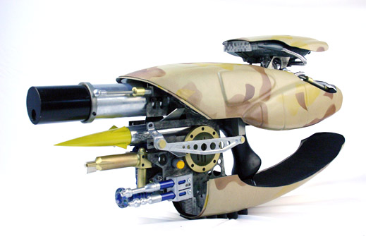
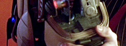
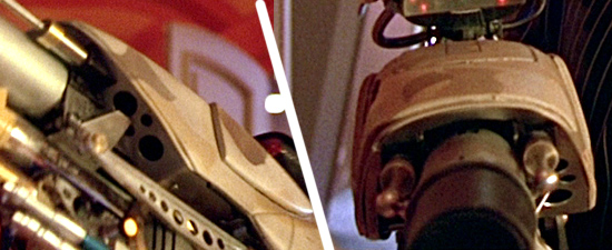
This tutorial will show you how to assemble a "Fhloston Paradise" ZF-1 replica as seen in the movie "The Fifth Element". The "Fhloston Paradise" model is the version that Zorg carried around the last half of the movie. The Scope was popped up, but the Replay Sensor and Arrow Pod doors were not.
This tutorial is based off the Superkrates "Mark II" ZF1 Kit. Currently Superkrates is offering "Mark III" kits. He is constantly revamping and upgrading his kit parts and we will try to note where things have drastically changed in the newer kits, and update images as time permits. Please bear with us.
This tutorial was photographed after Superkrates had built this particular Mark II replica, so he just tore it down for us, and re-assembled the parts, giving hints and tips along the way.
While our tutorial shows painted parts being assembled, you might want to assemble your kit without painting it, and then tear it down and paint the parts after you have everything fitting the way you like it.
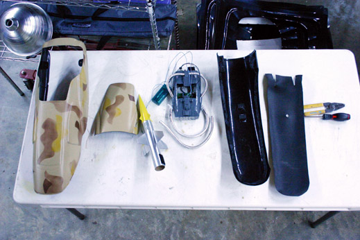
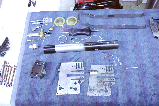
The ZF-1 disassembled...
(from left-to-right)- Upper Shell
- Scope Door
- Rocket
- Scope (with ribbed tubing and electronics)
- Bottom Shell
- Bottom Shell Floor Mat
- Wire strippers
- Screw Driver
- Allen Wrenches
- Various sized open-end Wrenches
- Blue Senors with Sensor Box.
- Flame Unit
- Flame Igniter
- Red Button (LED lit)
- Yellow Button (LED lit)
- Rocket Vents (brass colored circles)
- Horizontal Plate
- Pistol Grip
- Barrel Ring
- Barrel
- Bottom Shell U-Bracket
- Left Vertical Side Plate
- Right Vertical Side Plate
- Various screws, nuts, and bolts
(starting at middle of image)
- Scope Arms
- Scope Pneumatic Lift Rods
- Support Brackets (left and right)
- 9-volt Battery
- Barrel Pneumatic Push rods (1-of-2 shown)
- Various Screws and bolts
- Scope Mounting Plate (black)
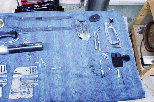
Items Not Shown:
- Blue Freeze Nozzle
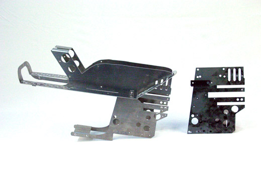
The skeleton of the ZF1... Vertical and Horizontal Plates!
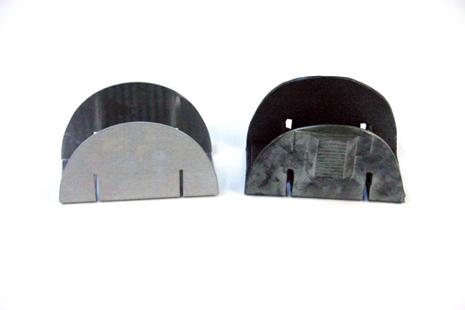
Here is an image of the Vertical Side Plates that Superkrates produces. Mark III (left) and Mark II (right) versions. (The Mark III plates have the Horizontal Plate attached to it). As you can see, the Mark II plates are the same design, but they do not go back along the length of the gun as far. Both configurations are accurate in their cuts, as you still get the same look in the finished product.
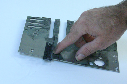
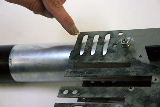
On each Vertical Side Plate you need to attach a long L-bracket along the back edge of the vertical wall. The bottom of this L-bracket should aline with the middle of the thin upper protrusion.
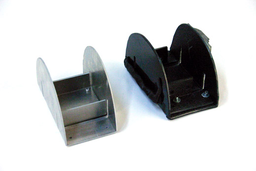
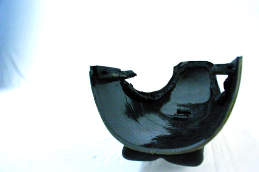
Bottom Shell U-bracket
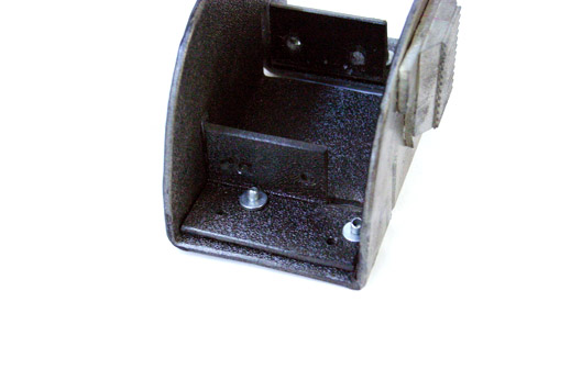
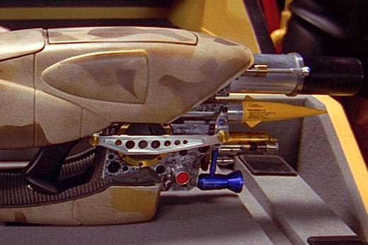
Now we'll assemble the Bottom Shell U-bracket. This bracket cradles the camouflage painted Bottom Shell, and actually holds most of the weight of the ZF1 replica.
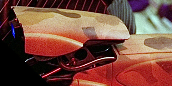
You will want to attach the correct model part from the Star Trek Voyager "Maquis Ship" model (made by Ertyl or Monogram) to the front of the U-bracket. We recommend epoxying or ABS glueing this model part to the front of the U-bracket.
Superkrates Mark III kit supplies the entire front plate, while this tutorial only used the T-shape part that's highly visible in screen captures from the movie.
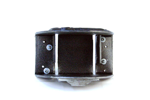
You can see two different Superkrates U-brackets here, one metal (aluminium) and one ABS plastic (black). The ABS plastic one is from a Superkrates Mark II kit, the metal bracket is from the Mark III kit (Mark III kits come in ABS or Metal, depending on your budget).
The main difference between the two versions is that the Mark III U-bracket gets a "secondary U-bracket" attached to the inside of the two horizontal slits, while the Mark II version uses L-brackets attached to the outside of the slits. The Mark III configuration allows for easier mounting of the Bottom Shell L-brackets that connect to the U-bracket later on.
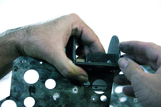
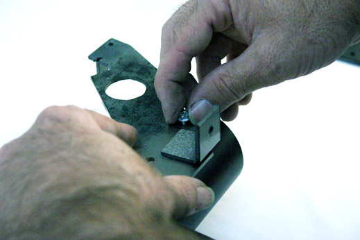
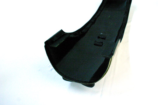
Here's a close up on the Secondary L-brackets used on the Mark II U-bracket
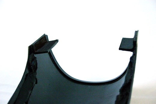
Notice that the Secondary brackets need to be set so that they do not impeded the slits in the U-bracket. The Vertical Side Plates will be slid into these slits.
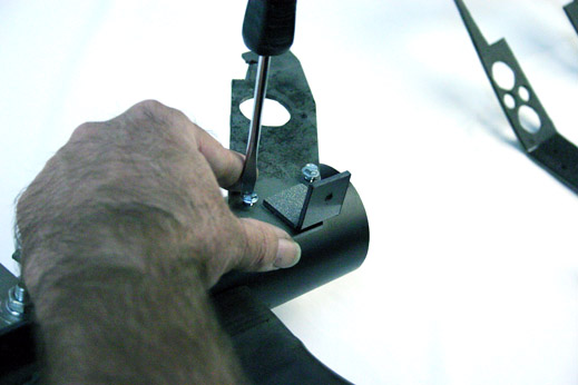
We'll slip the Vertical Side Plates into the Slits and bolt them to the Secondary Brackets.
Discussed in the "The Bottom Shell" section of this assembly guide, you can opt to attach the Bottom Shell 'L-brackets' to the Bottom Shell now, or you can do it later on. Be Warned Though: only attach the L-brackets to the shell, DO NOT try to attach the U-bracket to the bottom shell. It is too early in the assembly process and you might hinder access to something that needs to be attached before the Bottom Shell is attached.
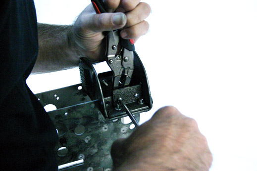
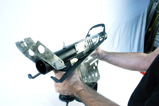
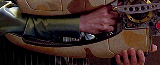
Attaching the Barrel and Pistol Grip
Next we attach the Pistol Grip to the PVC pipe that doubles as the Outer Barrel. If you are going to install an Airsoft AK-74 into your replica, you can skip this step (The blank-firing, movie-used ZF-1 had a full-auto AK-74 using a 30-round, Polish-made, metal banana clip).
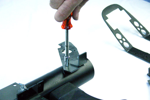
We carefully drilled a hole through the solid resin grip, allowing for a 1/4 inch All-Thread Rod to slip through. This Solid Rod ensures that the grip can take the full weight of the ZF-1 when finished.
Notice the nut and washer already attached to the bottom of the All-Thread.
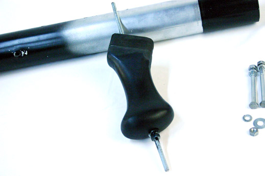
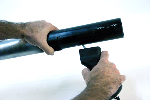
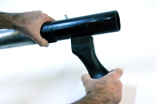
Notice that we sanded a curved valley into the top of the resin grip into ensure proper seating of the grip to the curved pipe.

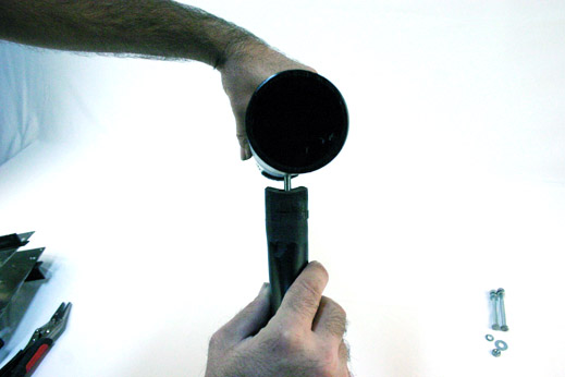
Screw a nut and washer on top. Tighten to a snug fit. (The resin grip may crack and fail if over tightened.)
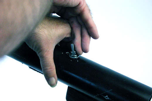
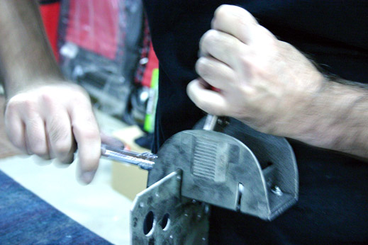
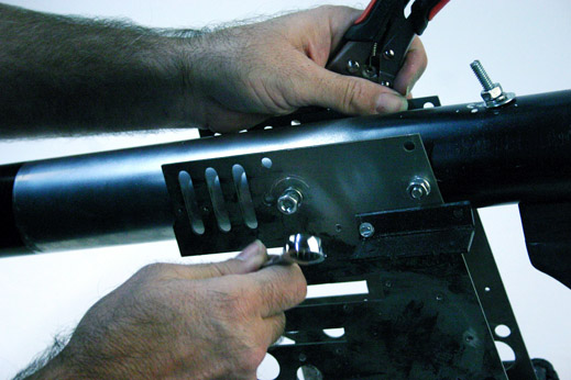
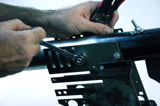
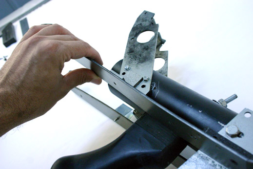
Now you can drill the holes and attach your pipe with grip to the Vertical Side Plates. Be careful to watch the vertical alignment of the grip as you drill your holes. If you drill the hole crooked, your grip could be cantered to the left of right, making the final product a little odd feeling when holding the ZF1 with one hand.
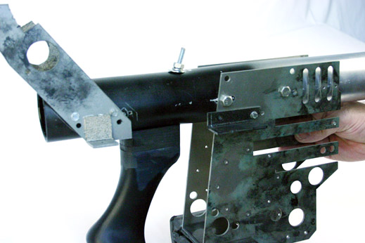
The Barrel should protrude out about 7.5 inches (19 cm) from the front edge of the Vertical Side Plates.
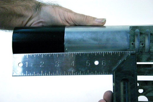
The Barrel runs parallel and flush to the bottom edge of the heat shield area of the Vertical Plate.
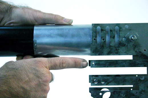
The side of the barrel should line up perfectly with the screw holes for the black brackets that hold the barrel pneumatics.
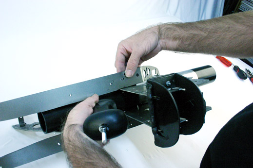
Attaching the Swing Arms for the Scope.
The Scope on the Fhloston Paradise model remained up at all times while on-screen in the movie, so we made our arms stationary. But, you can decide to make the pneumatic rods raise and lower the Scope. It's your decision.
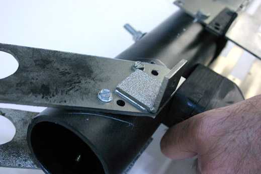
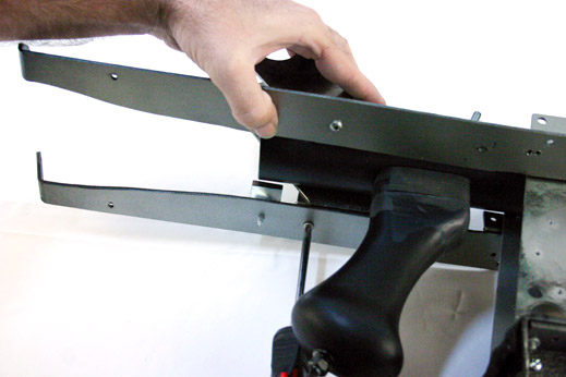
Did you notice the L-bracket attached to the bottom of the Swing Arm? This L-bracket holds the back end of the Horizontal Plates in place. If you animate the swing arm, you will need to figure out how to mount these L-brackets a different way. (Superkrates Mark III PLates account for this, so this is a moot point for that kit)
Mount both arms. Right and Left.
One again, the L-bracket on the back of the replica. In this image you can see how it lines up with the front L-bracket.
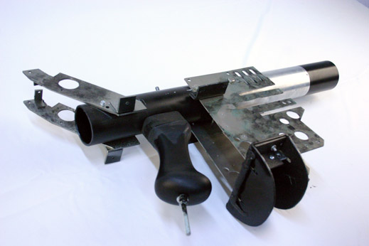
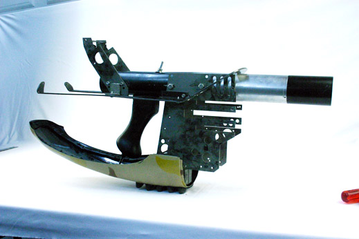
The replica in it's currently "assembled" state.
The Horizontal Plate
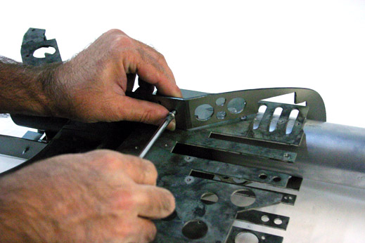
Now we will attach the Horizontal Plate.
The Horizontal plate attaches under the L-brackets on the side of the Vertical plates...
... NOT above the brackets.
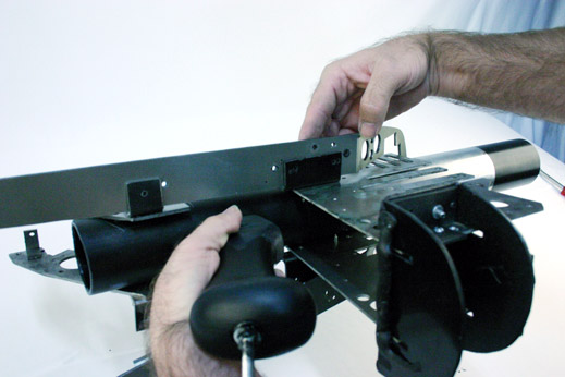
Mounting the plates on the bottom hides the bracket when the Upper Shell is placed on the replica later on.
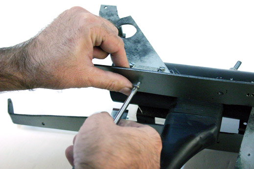
We'll use simple nuts and bolts to attach the horizontal plate to the L-brackets. If you want to die-tap the L-bracket and forego use of a nut, you can do that.
Attach all four L-brackets to the Horizontal plate.
The Bottom Shell
Now lets attach L-brackets to the Bottom Shell which are needed for mounting the Shell to the U-bracket.
Attach the brackets with Fiberglass Resin and Fiberglass Matte (if you are using a fiberglass shell), and use ABS glue if you are using a vacuumformed ABS plastic shell.
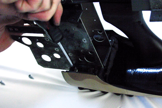
Now slip the U-bracket into the cradle-like area of the Bottom Shell, straddling the attached L-brackets.
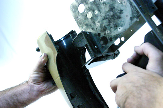
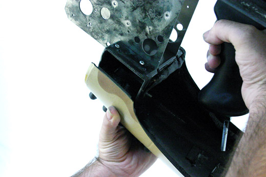
Mark, Drill and Tap the mounting points for the L-bracket, then bolt/screw the U-bracket to the Bottom Shell's L-brackets.
One of the main reasons why you want to attach the Bottom Shell now, before attaching any of the armaments to the Horizontal Plates, is "space". You would find it difficult to get a screwdriver down into this area to tighten these bolts with all those armament parts attached to the sides.
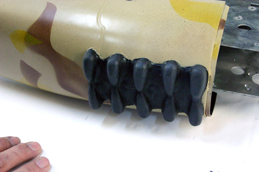
At this stage, you can glue the Bottom Foot to the bottom of the Bottom Shell, if you want.
If you do not have a clamp of some sort to hold the replica up during the rest of the assembly, then you want to attach the Bottom Foot. The attached foot will make painting the replica a hassle later on, but it does help stabilize the replica as you work on it.
The replica in it's "assembled state" at this stage.
You can also install the Bottom Shell Floor Mat now -or- later (as we have done in this tutorial).
!
Continue to:
ZF1 - Assembly: Page 2, Page 3, or Page 4
Do You Have Questions or Comments? Contact Us.
©2011 Studio Creations - All Rights Reserved